PQ TOOL SOP
1. SStar_PQ Tool Connection
1.1. Open PQ Tool
Double-click the icon to open it after installation.

Figure1-1 PQ tool icon
1.2. Close Serial Port Printing
Close serial port printing and disconnect before PQ Tool connect to the serial port for communication.
For Takoyaki series,input 11111 in the serial port printing window to stop it.
1.3. Chip Selection
According to the chip and board model you get, select the appropriate chip type in the table below.
Takoyaki selects SsInfinity Series.
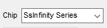
Figure1-2 Chip type option
1.4. Tool Configuration

Figure1-3 Configuration and Connection
Select the chip series according to the mark 1 in the figure, and then click the mark 2, which will turn into a green icon when the connection is successful. If not, make sure that the serial port printing is properly closed and disconnected, and then reconnect.
1.5. Read Register Value
Switch to the corresponding band first.
Select any subband.
Enter 0x101e and press Enter.
Click Read Bank.
Check the register value on the right, all zeros or all ffs indicate that the tool is not properly connected.
The reference value is shown in Figure 1-5.
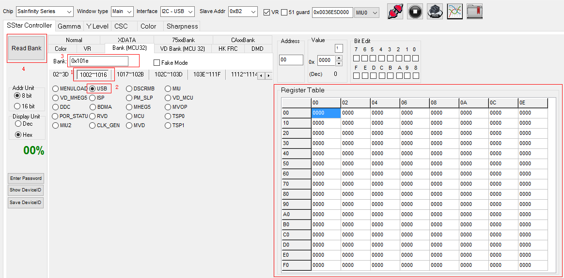
Figure1-4 Read register
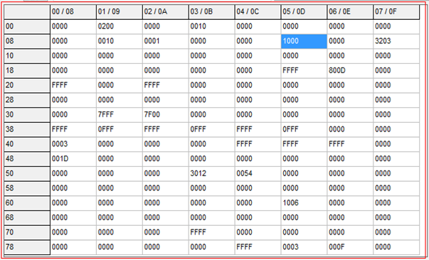
Figure1-5 Bank interface
2. Gamma Adjustment
2.1. Read The Original Settings Of The Board
Switch to the gamma subpage and click Read:

Figure1-6
2.2. Switch To The Write Page, Adjust The RGB Curve As Required
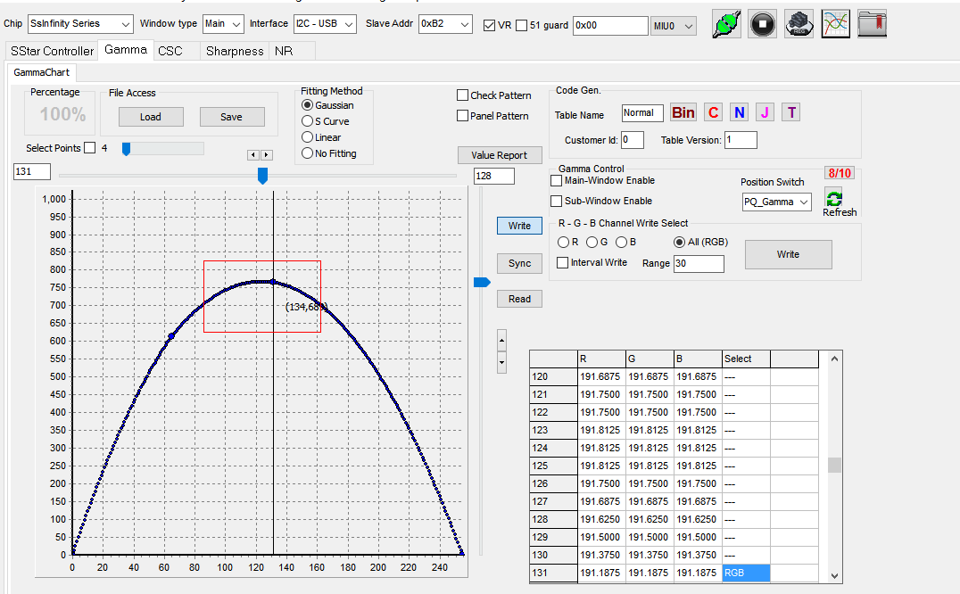
Figure2-2
Click write:
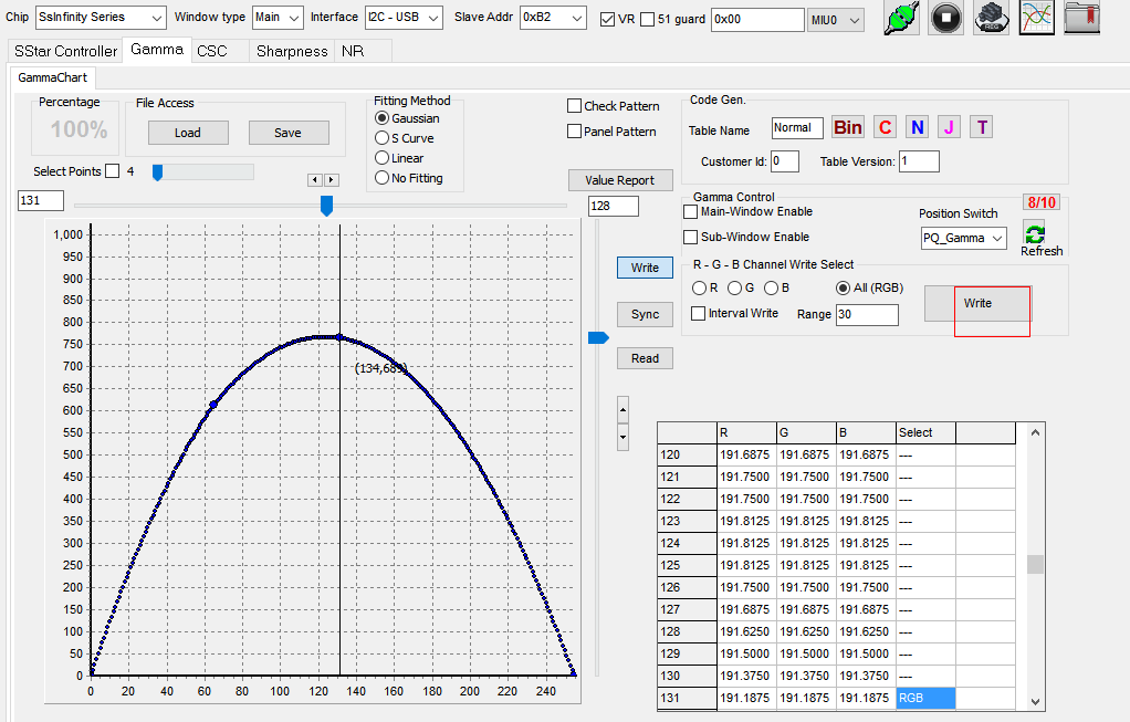
Figure2-3
2.3. Save gamma Configuration
Click the button to save the configuration as a TXT file.

Figure2-4
2.4. Write The Adjusted GAMMA Configuration File To The Board
Load gamma setting first:
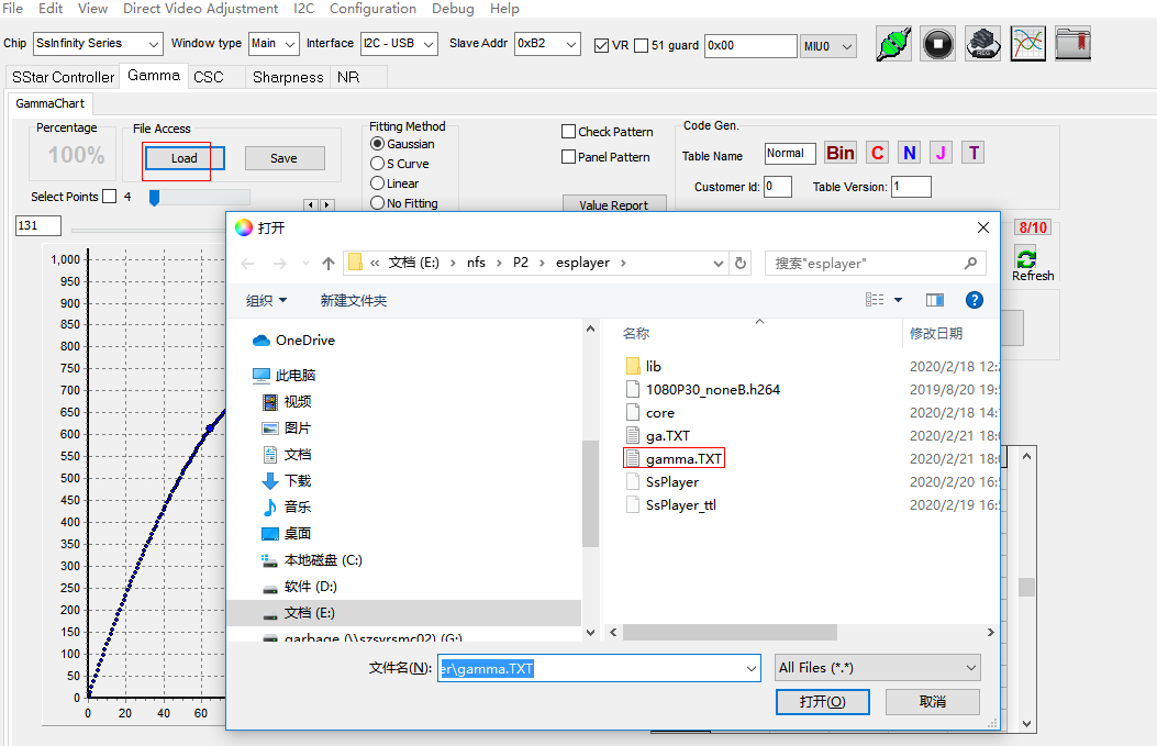
Figure2-5
Then write:
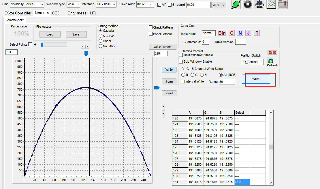
Figure2-6
The gamma configuration can also be written to the board through the serial terminal (the corresponding gamma file needs to be converted to unix format before writing):
echo gama.TXT 40 > /sys/class/mstar/mdisp/pq
3. CSC Adjustment
3.1. Write The Adjusted CSC Value
Switch to the csc page, adjust the csc value on the right, and click download on the left to see the effect.

Figure3-1
3.2. Save Current CSC Settings
Click GenMatrixTbl to save CSC table parameter of the board in CSC_Parameter.txt in PQ Tool root directory, copy the file to system, take effect after writing command as follow:
echo CSC_Parameter.txt 100 > /sys/class/mstar/mdisp/pq
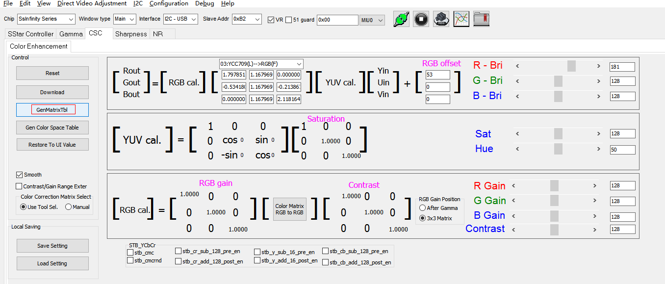
Figure3-2
如果是用工具调试也可以保存当前所有的csc设定,然后通过save setting保存当前csc设定:
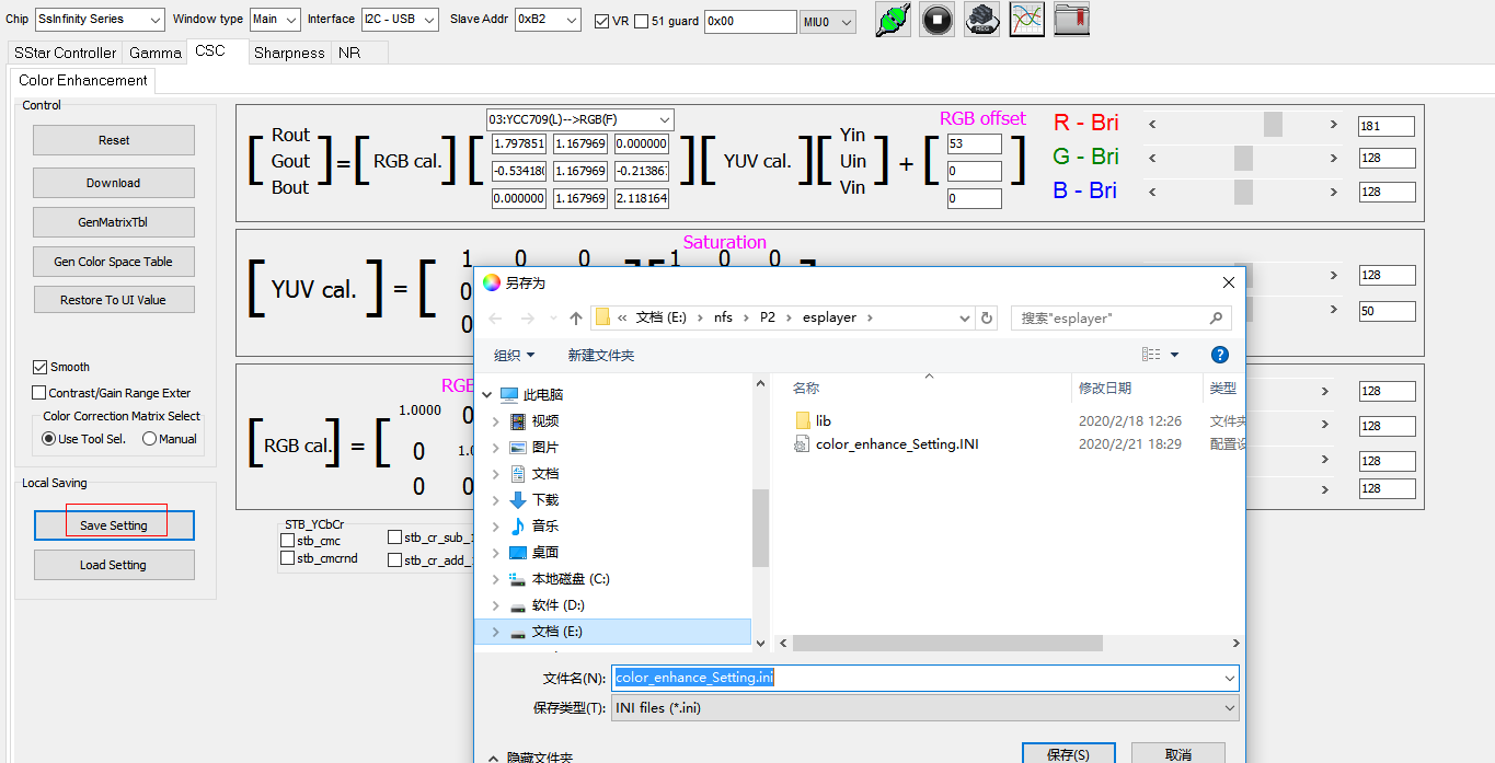
Figure3-3
Then load setting:
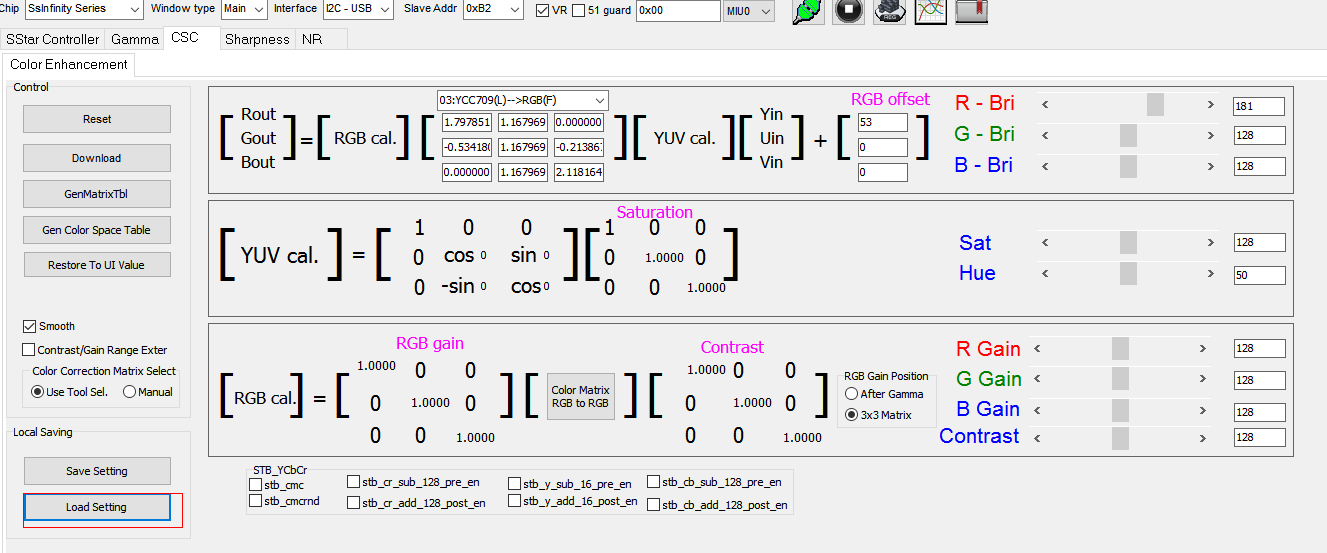
Figure3-4
3.3. Csc Specific Parameter Description
-
Switch to CSC subpage.
-
Resetis used to restore the current parameters to the initial. -
Downloadis used to write the parameters of the current debugging interface to the board. -
GenMatrixTblis used save the CSC table parameters of the current board in the tool`s root directory named CSC_Parameter.txt. Copy the file into system by the command below:echo CSC_Parameter.txt 100 > /sys/class/mstar/mdisp/pq -
Restore To UI Valueis used to read the current data and displayed on the interface. -
Save Settingis used to save the current parameters. -
Load Settingis used to import the parameters saved bySave Settingand displayed on the interface. -
RGB bri corresponds to RGB brightness
-
Satis short for saturation, used to modify the overall saturation. -
Hueis used to modify the overall tone. -
RGB gain means White Balance gain.
-
Contrastis used to modify the overall displayed contrast.
Figure3-5
4. Sharpness Adjustment
-
Tick
2D Peaking Enableto enable sharpness. -
Peaking_Bank_refresh will set the current HVB Band parameter as default value.
-
Save Peaking to file: Save the sharpness parameters of the current motherboard to the Sharp_Parameter.txt file in the local directory. The command is as follow:echo Sharp_Parameter.txt 8 > /sys/class/mstar/mdisp/pqIf it requires power-off and restart to take effect, manually overwrite the parameters in
CSC_Parameter.txtto the following corresponding position inpq.ini.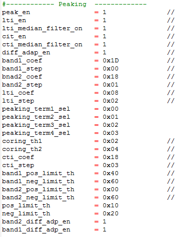
Figure4-1 Peaking Parameter
-
Save Settingis used to save the current parameter to local folder. -
Load Settingis used to import the local parameter and displayed on the interface but not be written on the motherboard. -
Adjusting the B01 and B02 parameters in H gain direction can modify the sharpness intensity in the horizontal direction.
-
Adjusting the B01 and B02 parameters in H Coring to improve the edge of the horizontal peaking adjustment.

Figure4-2 Sharpness
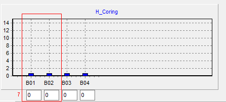
Figure4-3 H Coring
5. Appendix
Overwrite all adjusted PQ parameters to pq.ini, use the following serial port command to take effect all PQ adjusted items
echo pq.ini ffff > /sys/class/mstar/mdisp/pq
It is valid after the DISP device is initialized.
The instruction is for Takoyaki, the PQ tool modules not mentioned can be used but write is invalid.